


Sending tank up top mode delivery
1. Principle:
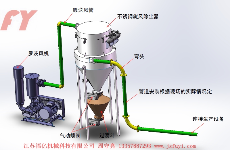
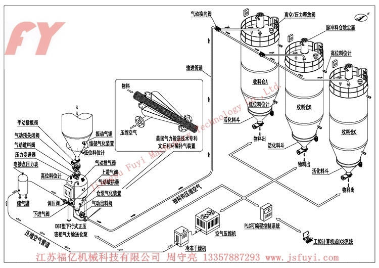
After the material is loaded into the sealed delivery tank, the compressed air enters from the top, bottom fluidizing plate and pressurization air of the sending tank, and the air passes through the air permeable barrier to make the material "boiling" to be fluidized. Because the pressure in the tank is sent, the fluidization material is sent through the inner delivery pipe.
2. Applicable material:
It has the characteristics of smooth transmission, high mixing ratio, widely used for conveying powder material with low proportion, such as powder, cement, fly ash, clay powder, flour, calcium carbonate, limestone powder, soybean powder, crushed rice husk powder etc.
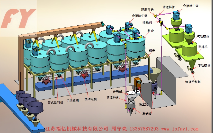
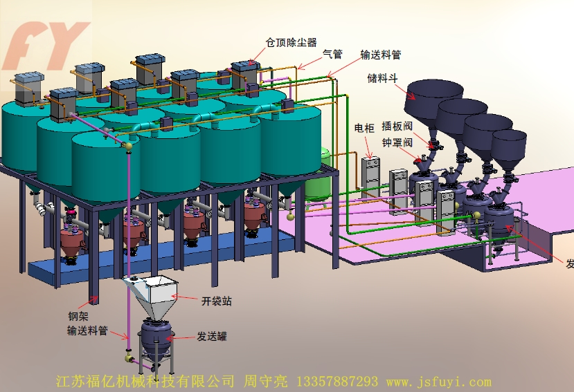
The boiling type pneumatic conveying device can design the delivery mode of the conveying pipe according to the structure, the material and the installation position of the flow plate at the bottom of the sending tank. According to the delivery position on the sending tank, it is roughly divided into the upper, the side and the side. Because of the different fluidization state of the material in the delivery tank, the instability of the conveying pipe will be caused, and the transportation capacity and mixing ratio will also change accordingly. According to the experiment, it is better to adopt the upper draft when the conveying distance is not long. The height of vertical pipe should be maintained at more than 5m, the material from the accelerated flow into steady flow.
On the boiling fluidized plate sending tank, sent at the bottom of the tank, the lower part of the feeding pipe flaring tube installed in the fluidized plate above the appropriate position of the top by sending top tank vertical, supercharged ejector installed in the pipeline at the outlet of the. The compressed air is divided into three: one from the top of the way into the sending tank at inlet, the ejector formed quickly back pressure, the material push down; two main road gas enters the fluidized plate at the bottom of the tank from intake sending tube, and the cut-off valve to regulate air flow into the intake pipe; three route booster ejector two, Qi Qi, the size can be adjusted to control the material gas mixture ratio. When the pressure value in the sending tank reaches the preset value, the delivery valve is quickly opened, and a high concentration gas mixture flow enters the delivery pipe and is smoothly transported out.
Side draught boiling type sending tank, the fluidization plate is obliquely arranged and the feeding tube on the side of the delivery tank, the material along the tilt direction of fluidizing plate conveying, the sending tank structure and horizontal separation of two horizontal, commonly used in bulk tank.
3. Main technical parameters of up draft tank
|
No. |
Name |
Specifications and parameters |
No. |
Name |
Specifications and parameters |
|
1 |
Delivery tank volume/m3 |
0.1-10.0 |
5 |
Working pressure/MPa |
0.1-0.4 |
|
2 |
Conveying capacity/t.h-1 |
1-50 |
6 |
Gas pressure/MPa |
≤0.6 |
|
3 |
Conveying distance/m |
<1000 |
7 |
Gas consumption/m3 |
1-35 |
|
4 |
Lifting distance/m |
<50 |
8 |
Feed valve combination / unit |
2-3 |
|
5 |
Cone angle of vertical tank |
35-70° |
|
Number of discharge points |
Site requirements |
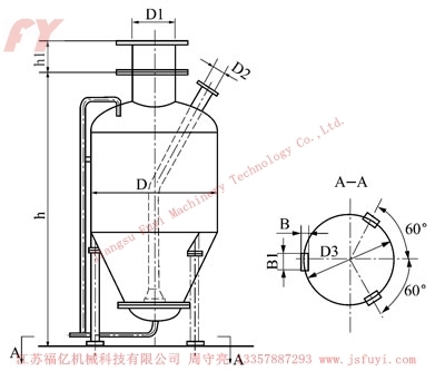
4. Series sizes of upward delivery cans
|
Type |
volume/m3 |
D |
D1 |
D2 |
D3 |
h |
h1 |
B*B1 |
|
CHP-1 |
0.1 |
500 |
150 |
40 |
40 |
1320 |
100 |
100*160 |
|
CHP-2 |
0.2 |
600 |
150 |
40 |
40 |
1320 |
100 |
100*160 |
|
CHP-4 |
0.4 |
800 |
200 |
60 |
50 |
1880 |
100 |
120*180 |
|
CHP-6 |
0.6 |
1000 |
200 |
80 |
65 |
2030 |
120 |
120*180 |
|
CHP-10 |
1.0 |
1000 |
250 |
80 |
65 |
2230 |
120 |
120*180 |
|
CHP-20 |
2.0 |
1400 |
250 |
125 |
80 |
2690 |
120 |
160*220 |
|
CHP-40 |
4.0 |
1800 |
300 |
150 |
100 |
3240 |
150 |
160*220 |


 简体中文
简体中文 English
 Español
 Русский
 Tiếng Việt